Our New Look
Check out our new look. Exciting..
YES! Passionate..YES! Complete..
NOT YET!


R.S.C. is proud to announce it's
new improved web presence look.
The new look will provide a way...
New Lines
R.S.C. is constantly expanding it's
lines for their customers. Give us a
call for any inquiries you may have.


We welcome Keywest Technology
as one of our newest product lines.
Keywest is a leader in the design,...
>

Speed Dome Camera Controller

Operation Manual

VER: 1.0

Please read this operation manual before using this device and use the device properly.
Also, please keep this manual with care to ensure easy access at any time.

SAFETY PRECAUTIONS


I. Summary

The keyboard controller is used for terminal receivers such as the intelligent Speed Dome and the decoder etc. Taking the EIA/RS-485 electrical interface between the keyboard and the receiver, one keyboard can control as much as 32 speed dome and decoders without driving the bus and the maximum communication distance between the keyboard and the receiver is up to 1.2 km. It’s very easy for operating and setting the Speed Dome Camera. The controller is also to control the terminal receiver to achieve the function of controlling pan/tilt, lens and etc.

Main Functions:

  1. 􀂋 Set the address range of the dome camera and the decoder064.
  2. 􀂋 Control all functions of the dome camera such as Power ON/OFF.
  3. 􀂋 To operate the pan/tilt of Speed Dome Camera moving in different speed lever
  4. 􀂋 Set or call the points of the dome camera. Altogether 64 preset points can be set.
  5. 􀂋 Manually or automatically control the dome camera, and change the settings of particular camera by

call the menu of the camera.

  1. 􀂋 Manually control the focus, zoom and iris of the camera.

II. Introduction of Functions

Select Camera0~64

Joystick Control Control Pan/Tilt direction and speed of the Speed Dome.

Lens Control Control the focus, zoom and iris of the camera.

Operation of Preset Position 1~64

Set Preset Position

Call Preset Position

Operation of Cruise Track1~6

Run Cruise Track

Automatic Horizontal Scan Control of dome (including speed and direction of scan)

Self-Learning Track of Intelligent Speed Dome

Function Setting of Menu of Speed Dome

Direct Control on Decoder Control front devices such as the decoder etc.

III. Introduction of the keyboard Panel

  1. 1. The Sketch of the Front Panel and Description of Buttons (Figure 1)

There are speed joystick, buttons and nixie light on the front panel of the control keyboard. The display is used to show the address of the speed dome as well as the number inputted. The joystick controls the upward, downward, leftward and right ward speed motion of the speed dome. The description of buttons is as follows:


    1. CAM Select address of the intelligent Speed Dome.
    2. MENU Auxiliary control buttons.
    3. AUTO To control auto-horizontal rotation for pan/tilt.
    4. CLEAR To clear inputted data
    5. 0-9 Number key
    6. WIDE To a wide angle.
    7. TELE To turn to a telescopic range.
    8. FAR To make focus far manually.
    9. NEAR To make focus near manually.
    10. OPEN To open iris.
    11. CLOSE To close iris.
    12. ON Switch on the setting of function.
    13. OFF Switch off the setting of function.
    14. CALL To call the preset position.
    15. PRESET To set the preset position.
    16. SHOT To call cruising track.

2. Rear Panel (Figure 2)

IV. Setting of the Keyboard

a) The protocol in use and the baud rate of communication of the keyboard are set by the ID-Code in Figure 2. DIP1-DIP4 are used to select type of the communication protocol as per following table.

PROTOCOL

TYPE

PROTOCOL SELECT

BAUD RATE SELECT

DIP-1

DIP-2

DIP-3

DIP-4

DIP-5

DIP-6

SAMSUNG

ON

OFF

OFF

OFF

OFF

ON

COP-2

ON

OFF

OFF

OFF

OFF

ON

Santachi

OFF

ON

OFF

OFF

OFF

ON

PELCO-D

ON

ON

OFF

OFF

OFF

OFF

PELCO-P/4800

OFF

OFF

ON

OFF

ON

OFF

PELCO-P/9600

OFF

ON

HUNDA600

ON

ON

ON

OFF

OFF

ON

COP-1

OFF

ON

ON

ON

OFF

ON

b) DIP5 and DIP6 are used to select the baud rate, shown as following table(DIP7 and DIP8 are not used)

Status of ID-Code

Baud Rate

DIP1

DIP2

DIP3

DIP4

DIP5

DIP6

DIP7

DIP8

2400bps

OFF

OFF

4800bps

ON

OFF

9600bps

OFF

ON

19200bps

ON

ON

c) Some of the ID-Code of the protocols are set as follows:

V. Operation of the Keyboard

        1. Select Address of Speed Dome Camera /Decoder [N]+[ CAM] Description N –– No. of camera from 0 to 64

    Function Select the address of the camera to be controlled. When the value N is in conformity with the address of the speed dome, it will be under control.

        2. To set preset position [N]+[ PRESET]

    Description N –– No. of preset position from 1 to 64.

        Function Store current position and refer it as No. N position.

        3. Call the Preset position [N]+[ CALL]

Description: N –– No. of preset position from 1 to 64.

Function Transfer the camera to the position of No. N preset position.

        4. Cancel the Preset position: [N]+[CLEAR]

Description N –– No. of preset position from 1 to 64.

Function Delete the No. N Preset position stored.

5. Run patrol [N]+ [SHOT]

Description N –– No. of the track from 1 to 3.

Function Tour the No. N track and stop tour by pushing the joystick.

        6. To turn on Auto Pan (Operation of COP-2 SAMSUNG Protocol) [AUTO]+[P1]+[ON]+[P2]+[OFF]

Description P1 –– the starting scan No. of preset point from 1 to 64, which should be set already.

                    Description P2 – the ending scan No. of preset point from 1 to 64, which should be set already. If P1 = P2 or P1 and P2 are coincided, the speed dome will make scan in range of 360°.

Note:For PELCO-DPELCO-PCOP-1 Protocol the way of operation is as follows:

    1. 􀂋 Set the starting scan position: Transfer the Speed Dome to the starting scan position, operation

[AUTO]+[ON]

    1. 􀂋 Set the ending scan position: Transfer the Speed Dome to the ending scan position, operation

[AUTO]+[OFF]

    1. 􀂋 Run Auto Pan[AUTO]+[SHOT]

Auto Pan operation takes the following parameters. You must set these parameters before using a

Auto Pan command to begin the scan operation. You can use the scan stop command or PT swing

stop command to stop the scan. Setting scan condition.

    1. 􀁺 Auto Pan Position (First specify position, second specify position)
    2. 􀁺 Auto Pan Speed and Direction

7. Stop Auto Pan[AUTO]+[OFF] ( Only C0P-2 Available) or push the joystick to stop scan

8. Patrol setup (COP-1, COP-2, PELCO-D, PELCO-P Available)

    1. a) Set Patrol Start[96] + [CALL] Begin to set the No.1 patrolLED Display L1

[97] + [CALL] Begin to set the No.2 patrolLED Display L2

[98] + [CALL] Begin to set the No.3 patrolLED Display L3

    1. b) Insert preset point in patrolif LED display LNN: No. of the patrol from 1 to 3.you can insert preset point in current patrol. Now you can operate as follow:

[N] + [CALL] (N: No. of preset position from 1 to 64). And you can insert 16 preset point in maximum

    1. c) Set Patrol Stop: [99] + [CALL]

9. Control the zoom of the Camera[WIDE]/[TELE]

10. Control the Focus of the Camera[FAR]/[NEAR]

11. Control the Iris of the Camera[OPEN]/[CLOSE]

12. Auxiliary Control of the CameraBy combination of [MENU] and [ON], [OFF] buttons, you can set some data of the camera, and functions are listed as follows (operations of COP-2 Protocol):

No. of Value N

Control Object

[MENU]+N+[ON]

[MENU]+N+[OFF]

0

Camera power supply/reset control

Power ON/OFF Switching

(Invalid in COP-1)

Recover Initial Values of Camera

1

Back Light Compensation

ON

OFF

2

Zero Illumination (refer to function of camera)

ON

OFF

3

Menu/Display (refer to function of camera)

ON

OFF

4

Digital Zoom

ON

OFF

5

Reserved

6

Focus (Invalid in COP-1)

Automatic

Manual

7

Iris

Automatic

Manual

8

White Balance ModeWB

Automatic

Manual

9

Indoor Mode

Outdoor Mode

10

ATW Mode

One Push WB

11

Black & White/Color Switching

(Invalid in COP-1)

Color

Black & White

12

Set Auto Pan (Only conditions for scan. If start scan, operate as Item 6 in this paragraph)

< 180°, low speed

> 180°, low speed

(Invalid in COP-1)

13

< 180°, middle speed

> 180°, middle speed

(Invalid in COP-1)

14

< 180°, high speed

> 180°, high speed

(Invalid in COP-1)


  1. 􀁺 For different camera, control functions in the list could be different.
  2. 􀁺 For the camera with the menu, switch ON/OFF the menu by "[MENU]+[3]+[ON]", and switch ON/OFF the OSD by "[MENU]+[3]+[OFF]". In case the camera has the menu and the menu is ON
    1. 1. Select the item on the menu by buttons [WIDE]/[TELE] to scroll the cursor up or down;
    2. 2. Chang the status of the selected item on the menu by buttons [FAR]/[NEAR];
    3. 3. Switch OFF the menu as per operations in the list after the menu is set.
  3. 􀁺 Take care of differences between the Menu of Speed Dome and the Menu of Camera. For the speed dome with the menu, enter the menu by "[64] +[CALL]" and basic operations are as follows
    1. 1. Call No.64 preset point to open the main menu by the control keyboard.
    2. 2. When the menu appears on the screen, move the cursor to the item you need to set by "TILT UP" and "TILT DOWN", and enter the settings of the item to make change by "PAN LEFT" and "PAN RIGHT";
    3. 3. Speed up operation of the joystick after keeping it for one second in one direction.
    4. 4. All settings of the menu could not be lost even power failure occurred;
    5. 5. Operations under special case can be referred on the description of the menu of the ball machine.

12. Use the Joystick to Control the Speed Dome Camera

You can use the speed joystick to control the Pan/Tilt direction and speed of the dome of the camera randomly. The speed of pan/tilt is decided by the angle of the joystick you operated (Figure 3). Change the tilting angle of the joystick you can adjust the speed evenly and the camera can be focused automatically in the course of scan to keep images being distinct.

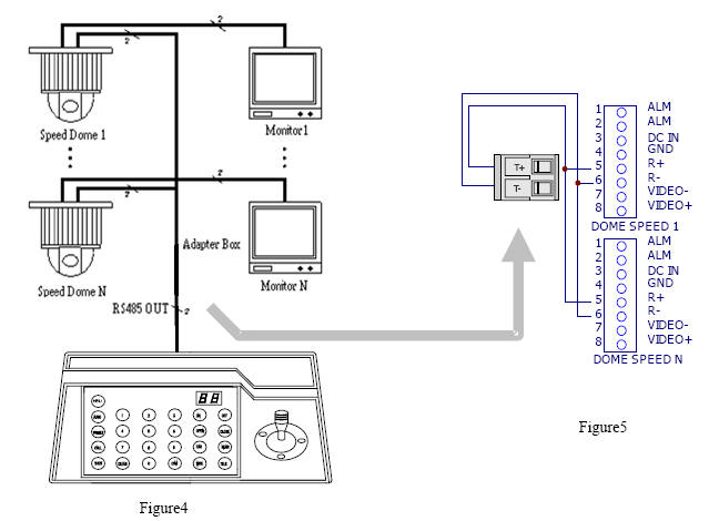
VI. Installation and Connection

Attention: Please read the operation manual of the keyboard and the speed dome carefully before connecting wires. Any incorrect connections can cause permanent damage of the device. When connecting wires, first switch off the power supply of all devices. The communication wires between devices should be shielded twisted cable. When installing cables they should be far away from high voltage lines or other possible interference circuits as can as possible.

1. Connections of the keyboard controller controlling multiple speed dome cameras (figure4)

2.Connections between the keyboard and the speed dome camera (Figure5)

VII. Technical Specifications

  1. 􀂋 Communication between Speed Dome Camera and ControllerPort to multi-port and half duplex function.
  2. 􀂋 Communication connector: RS-485.
  3. 􀂋 Baud Rate of CommunicationFour baud rates i.e. 2400Bps, 4800Bps, 9600Bps and 19200Bps.
  4. 􀂋 Distance of Communication1200 M in maximum
  5. 􀂋 Power Supply500 mAthe input voltage of power supply is variable for power supply’s specification
  6. 􀂋 Size188 × 97 × 70mm
  7. 􀂋 Weight0.5 Kg
  8. 􀂋 Number of Controlled Speed Dome Camera up to 32.

VIII. Points for Attention

  1. 􀂋 Please read the operation manual of the keyboard carefully before using it.
  2. 􀂋 The operation manual is mainly focused on all functions of COP-2 Protocol. For other different protocols, operations could be something difference and those different parts will be listed on "Supplementary Description of the Keyboard Controller" in details.
  3. 􀂋 The keyboard takes 12V DC power supply. Please confirm the voltage and polarity before the power supply is switched on.
  4. 􀂋 Do not place the keyboard under the rain or on wet place so as to avoid short circuit or electrical shock.
  5. 􀂋 As the keyboard is a sophisticated electronic device, you should never open the case so as to avoid the occurrence of trouble.
  6. 􀂋 The keyboard has integrated multiple protocols, and you are pleased to select correct protocol and the baud rate.

ZOOM CAMERA CONTROL OPERATION FOR 15-CZ45 & 15-CZ55

.15-CZ45: ZOOM CAMERA

1. PROTOCOL OF 15-CZ45 (COP-03): SEE PAGE 3. IV. SETTING OF THE KEYBOARD

2. CAMERA ADDRESS : [CAM]+[N1]+ON+[N2]+OFF

2-1. N1: EYBOARD CONTROLLER DISPLAY CURRENTLY CAMERA NO.

2-2. N2: INPUT NEW CAMERA NO.

2-3. CAMERA NO. FROM 1 TO 7

  1. 3. CHOOSE CAMERA NUMBER: [N]+[CAM]+[ENTER]
  2. 4. ZOOM: [WIDE] OR [TELE]
  3. 5. FOCUS: [FAR] OR [ NEAR]
  4. 6. IRIS: [OPEN] OR [ CLOSE]

. 15-CZ55: ZOOM CAMERA

1.PROTOCOL OF 15-CZ55 (COP-04): SEE PAGE 3. IV. SETTING OF THE KEYBOARD

2. CAMERA ADDRESS : [CAM]+[N1]+ON+[N2]+OFF

2-1. N1: EYBOARD CONTROLLER DISPLAY CURRENTLY CAMERA NO.

2-2. N2: INPUT NEW CAMERA NO.

2-3. CAMERA NO. FROM 1 TO 64

3.CHOOSE CAMERA NUMBER: [N]+[CAM]+[ENTER]

4.ZOOM: [WIDE] OR [TELE]

5.FOCUS: [FAR] OR [ NEAR]

6.IRIS: [OPEN] OR [ CLOSE]


R.S.C. Broadband Supply Co. © 2006 • Privacy Policy Terms Of Use